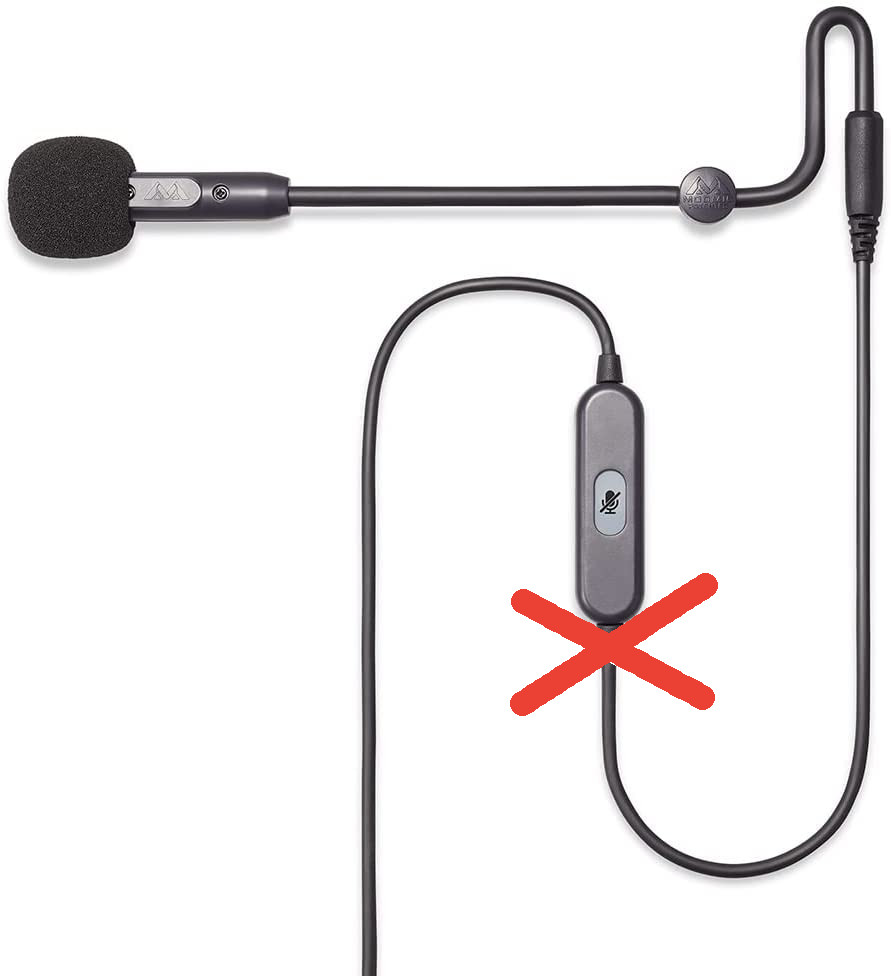
Using Christmas 2020 as an opportunity to imporve my home office setup, I got myself a nice dedicated Antlion USB ModMic. Knowing that Bluetooth microphones sometimes are a bit troublesome under Ubuntu, I got the wired version. A wire which I accidentally rolled over with my office chair, ripping the microphone itself out of the integrated mute button.
Since I really liked the mic (and didn’t want to buy a new one) I of course tried to fix it. Prying open the mute button case was fairly easy with a knife. I’m only documenting this as an afterthought so I didn’t take better pictures. But basically, 3 wires (VCC, GND, Signal) go from the mic to the button from which on a fourth (The mute state?) go into the PC. Vaguely remembering that it apparently is good practise to have the GND and VCC pads on separate sides of the PCB, I just guessed the correct pads and soldered things back into place.


Since I couldn’t find the circuit diagram for the mute button PCB anywhere, I thought I’d document the correct pads here. After verifying that it works, I just fiddled everything into the case again and pressed it shut. That was fairly easy. Yey!

Hi ya – I’ve got one recently and although not broken want to unify the mic and headphone cord into one, so thinking of cutting the cable off and wiring into headphone socket. I’m new to all this. You mention 4 wires but only mark 2 at one end and 3 at the other. Is the 4th a second ground?
Hey Andy, I’m not fully sure if I understand your goal. So from my very limited understanding of this microphone, it goes roughly like this
red = VCC, black = GND, green = signal, dashed = mute
with 3 wires coming from the actual microphone and then one additional wire going into the computer after the mute button. So my suspicion is that the “new” white wire is that mute-button and the green/yellow one is the microphone signal.